
Cartridge KTM Rotaflex
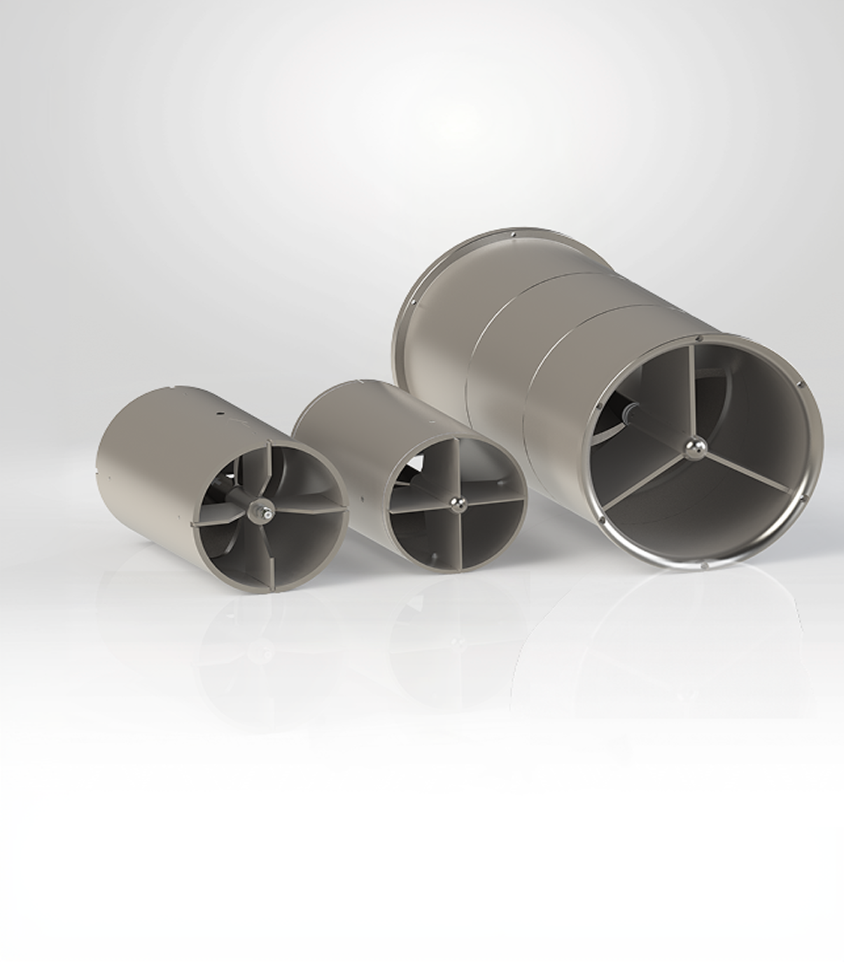
Commercial and process metering of liquids
Advantages:
- KTM ROTAFLEX turbine flow meter replaceable module, designed as a separate cartridge for ease of maintenance and quick replacement without altering the flow meter body;
- Operation in non-hazardous and hazardous areas (Zones 0, 1, and 2) involving gas atmospheres, in accordance with GOST 31610.0‑2019, GOST ISO/DIS 80079‑37‑2013, and GOST 32407‑2013;
- The pressure limit is determined by the permissible pressure for the flow meter in which the cartridge is used, as well as by the chemical properties of the working medium in relation to the pressure specified by the customer;
- High measurement accuracy: maximum permissible relative error of ±0.15%; standard deviation of the random error component of 0.02%.
- Wide flow rate range for DN 250: minimum 90 m³/h and maximum 2200 m³/h, depending on the configuration and turbine material. For DN 400: minimum 310 m³/h, maximum 4500 m³/h.
- Operating medium temperature range: from -45 to +180°C;
- Permissible kinematic viscosity of the working medium: up to 100 cSt for DN250, up to 160 cSt for DN400;
- Capability to replace cartridges of foreign flow meters—specifically «MVTM Smith Meter» (DN250), «Heliflu TZN» (DN250), and «Heliflu TZN» (DN400)—while maintaining the design, dimensions, and functionality of the corresponding model;
- Use of corrosion-resistant materials for the housing and stators (titanium, aluminum alloy, stainless steel, carbon-fiber-reinforced composite); (Subject to agreement with the customer and/or the requirements of the supply contract, components may be manufactured from materials other than those specified, provided that approval is obtained from the certifying organization);
- Enhanced reliability: mean time between failures of at least 70,000 hours; designated service life of 10 years.
Technical specifications
|
Parameter name |
Parameter value |
|
|
Maximum working pressure, kPa |
The pressure limit is restricted by the permissible pressure for the flowmeter incorporating the cartridge, as well as by the chemical properties of the working medium, which depend on the pressure specified by the customer |
|
|
Working medium |
oil, petroleum products, oils, water, glycols, glycerin, heat transfer fluids, chemicals, industrial liquids |
|
|
Ambient (working) temperature, °C |
from minus 45 to plus 180 |
|
|
Maximum kinematic viscosity of the working medium, cSt |
100¹ |
160² |
|
Ex marking |
0Ex h IIB Т6…Т2 Ga X |
|
|
Recommended filtration of the working medium, mm |
not more than 2 |
|
|
Designated service life, years |
10 |
|
|
Mean time between failures, h |
not less than 70,000 |
|
|
Notes ¹ For DN250. ² For DN400. |
||
Compatibility with flowmeters
|
Cartridge version designation |
Nominal bore diameter, mm |
Compatible flowmeter model |
Connection diagram of magnetic induction sensors (MIS) *) |
Typical code in cartridge designation |
|
Type M |
250 |
КТМ ROTAFLEX 250-Х-Х-1-…; «MVTM Smith Meter» DN250 |
Scheme No.1 |
250-Х-1-1 |
|
Scheme No.2 |
250-Х-2-1 |
|||
|
Scheme No.3 |
250-Х-3-1 |
|||
|
Scheme No.4 |
250-Х-4-1 |
|||
|
Scheme No.5 |
250-Х-5-1 |
|||
|
Type H |
250 |
КТМ ROTAFLEX 250-Х-0-3-…; «Heliflu TZN» DN250 |
Does not affect cartridge version |
250-Х-0-3 |
|
400 |
КТМ ROTAFLEX 400-Х-0-3-…; «Heliflu TZN» DN400 |
400-Х-0-3 |
||
|
* It is allowed, upon agreement with the customer and/or as required by the supply contract, to manufacture cartridges with MIS connection diagrams different from those specified, provided that the certifying organization agrees. |
||||
Type M cartridges have additional design differences for various sensor connection diagrams depending on their number and arrangement, as follows:
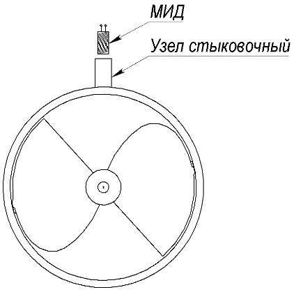
- one sensor – Scheme No.1;
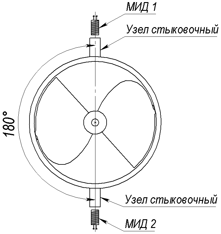
- two MIS, positioned at a 180° angle – Scheme No.2;
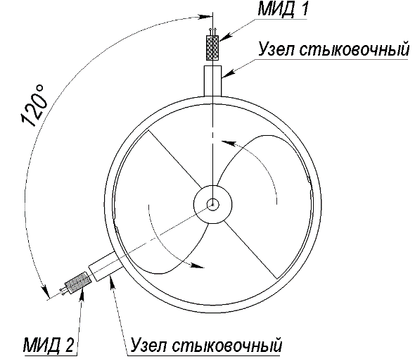
- two MIS, positioned at a 120° angle – Scheme No.3.
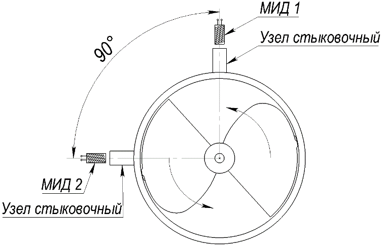
- two MIS, positioned at a 90° angle – Scheme No.4.
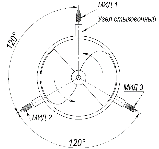
- three MIS, positioned at a 120° angle – Scheme No.5.
MIS connection diagrams
|
Scheme No.1 |
Scheme No.2 |
Scheme No.3 |
|
 |
 |
 |
|
|
Scheme No.4 |
Scheme No.5 |
||
 |
 |
||
Cartridge version specifications
|
Parameter name |
Parameter value |
|||||||||||
|
Cartridge version designation |
Type M |
Type H |
||||||||||
|
Nominal bore diameter, mm |
250 |
250 |
400 |
|||||||||
|
Turbine material according to designation as per Appendix B in the Operation Manual (in the documents section) |
0 |
1 |
2 |
3 |
0 |
1 |
2 |
3 |
0 |
1 |
2 |
3 |
|
Maximum volumetric flow rate of the working medium, m³/h |
1990 |
1194 |
2100 |
2000 |
2000 |
1200 |
2200 |
2000 |
4000 |
3400 |
4500 |
3800 |
|
Minimum volumetric flow rate of the working medium, m³/h |
199 |
119 |
350 |
100 |
200 |
120 |
230 |
90 |
400 |
340 |
450 |
310 |