Fluid Flow Meter UZS-1М ®
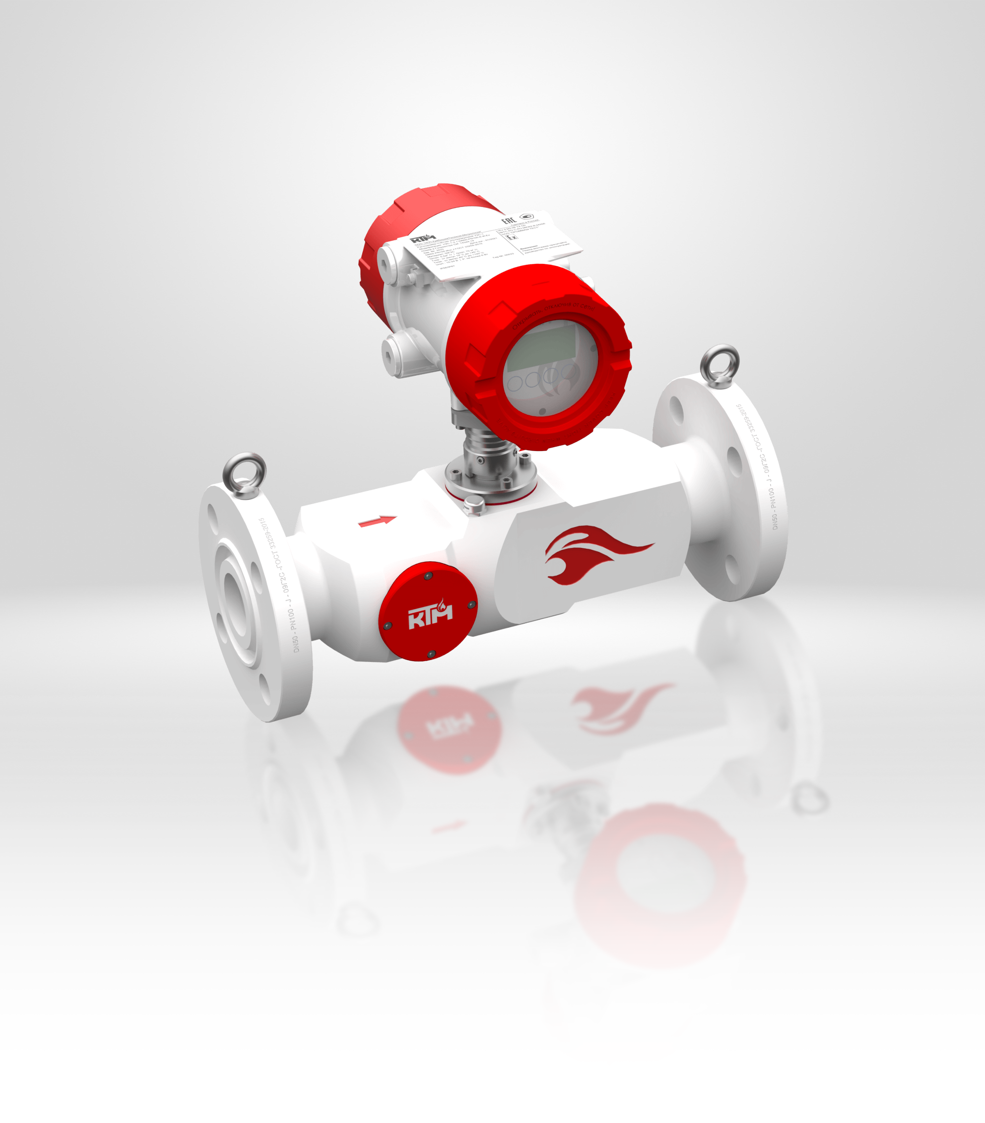
Commercial and technical metering of fluids
Benefits:
- Lubricator design for mounting on a pipeline without flow stop (where metering is required, but flow in the pipe cannot be “stopped”);
- Operating pressure (excess) to 50 МPа (turned solid design);
- Metering of CNG and other compressed gases to -196°C;
- Metering of high temperature fluids tо +300°C/450°C;
- Metering of high viscosity fluids (masut, tar), steam jacketed version;
- Pipeline nominal diameter from 8 mm tо 3000 mm;
- Measurement error ± 0.28%/ ± 0.5%/ ± 1%;
- Compensation of housing geometric size change by temperature and pressure;
- Separate calculation for the Customer and the Consumer with two independent meters in one housing;
- Calibration interval – 5 years, service life – 15 years.
METROLOGY AND TECHNICAL CHARACTERISTICS
| Parameter name | Parameter value | Remark |
|---|---|---|
| Internal pipe diameter, mm |
from 8 to 1400 from 100 to 3000 |
Measurement site (MS)
Mounting kit without MS |
| Length of straight sections |
5 х DN 10 х DN 15 х DN |
If an orifice box is available
After leadaway in 1 plane After leadaway in 2 planes |
| Operating medium flow rate, m/s | 0.03…20 | |
| Operating medium excess pressure, МPа | to 50 | |
| Medium temperature, 0С
Design T1 Design T2 Design T3 Design T4 Design T5 Design T6 Design T7 Design T8 |
-45… +450 -45… +300 -200…+180 -60…+135 -60…+100 -60…+85 -45…+550 -10…+80 |
|
| Permissible gas content in liquid (volume fraction),% | ≤ 3 | |
| Permissible mechanical impurities content in fluid (by volume), % | ≤ 5 | |
| Máximum medium viscosity, сST
Design V1 Design V2 |
tо 300 tо 1000(3) |
|
| Number of measurement beams | 1, 2, 3 | |
| Flow rate measurement relative error, % | 1
0.5 0.28 |
1 beam
2 beams 3 beams |
| Calibration interval, years | 5 | |
| Transmitters-receivers mounting angle, 0 | 45, 60 | |
| Operation frequency of ultrasound transmitters-receivers, MHz | 1.5 2 |
With deviation ±5% |
| Ambient temperature, 0С | -40…+60 -70… +85(1) |
|
| Storage temperature, 0С | -50…+70 | |
| IP degree of protection | 66/68 | |
| Explosion-proof marking | 1Exd [ia Ga] IIC T6…T2 Gb X | Zone 1, 2 |
| Outputs and interfaces | RS-485
0-20 mА, 0-5 mА, 4-20mА Pulse-frequency |
with support of Modbus RTU, Modbus ASCIICurrent loop with support of HART passiveto 10 kHz, NAMUR NE107 Profibus gateway to ModbusRTU Fieldbus gateway to ModbusRTU |
| Direct current power voltage, V Alternating current power voltage, V |
Nominal 24 V (12…30)
Nominal 220 V (187…242) |
With AC-DC module |
| Input power: Direct current, W Alternating current, V*А |
6 11 |
|
| Mean time to failure term, h | 120000 | |
| Service life, years | 15 |
(1) With the use of heating devices for the Processing Unit
(2) With the use of heating devices for the Processing Unit
(3) Extended range by temperature, pressure, and viscosity
Standard sizes and flow ranges
| Nominal diameter, DN (mm) | Flow rate, m3/h | |
| Qmin | Qmax | |
| 8 | 0,0054 | 3,62 |
| 10 | 0,0085 | 5,65 |
| 12 | 0,0122 | 8,14 |
| 15 | 0,0191 | 12,72 |
| 20 | 0,0339 | 22,62 |
| 25 | 0,05301 | 35,34 |
| 32 | 0,0869 | 57,91 |
| 40 | 0,136 | 90,48 |
| 50 | 0,212 | 141,37 |
| 65 | 0,358 | 238,92 |
| 80 | 0,543 | 361,91 |
| 100 | 0,848 | 565,49 |
| 125 | 1,325 | 883,60 |
| 150 | 1,909 | 1 272,30 |
| 200 | 3,393 | 2 261,90 |
| 250 | 5,301 | 3 534,30 |
| 300 | 7,634 | 5 089,40 |
| 350 | 10,391 | 6 927,20 |
| 400 | 13,57 | 9 047,80 |
| 450 | 17,18 | 11 451,10 |
| 500 | 21,21 | 14 137,20 |
| 600 | 30,54 | 20 357,50 |
| 700 | 41,56 | 27 708,80 |
| 800 | 54,29 | 36 191,10 |
| 900 | 68,71 | 45 804,40 |
| 1000 | 84,82 | 56 548,70 |
| 1200 | 122,15 | 81 430,10 |
| 1400 | 166,25 | 110 835,40 |
| 1600 | 217,15 | 144 764,60 |
| 1800 | 274,83 | 183 217,70 |
| 2000 | 339,29 | 226 194,70 |
| 2200 | 410,54 | 273 695,60 |
| 2400 | 488,58 | 325 720,30 |
| 2600 | 573,40 | 382 269,00 |
| 2800 | 665,01 | 443 341,60 |
| 3000 | 763,41 | 508 938,00 |